
 Kia Sportage: Heater Unit: Repair procedures
Kia Sportage Service & Repair Manual (3rd Generation, SL; 2011-2016) / Heating,Ventilation, Air Conditioning / Heater / Heater Unit: Repair procedures
| Replacement |
| 1. |
Disconnect the negative (-) battery terminal. |
| 2. |
Recover the refrigerant with a recovery/ recycling/ charging station. |
| 3. |
When the engine is cool, drain the engine coolant from the radiator. |
| 4. |
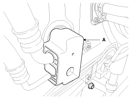
Remove the expansion valve cover (A).
|
| 5. |
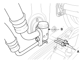
Remove the bolts (A) and the expansion valve (B) from the evaporator core.
|

| 6. |
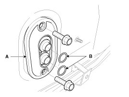
Remove the expansion valve flange (A).
|
| 7. |
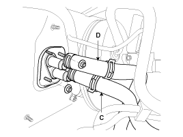
Disconnect the inlet (C) and outlet (D) heater hoses from the heater unit.
|
| 8. |
Remove the cowl top cover.
(Refer to BD group - "Cowl Top Cover"). |
| 9. |
Loosen the cowl cross member mounting bolts (A).
|
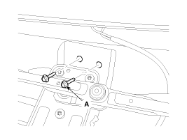
| 10. |
Remove the steering handle and column.
(Refer to ST group - "Steering Column") |
| 11. |
Remove the center console.
(Refer to BD group - "Center Console") |
| 12. |
Disconnect the airbag connector (A).
|
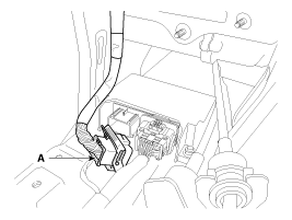
| 13. |
Disconnect the connectors and then remove the left & right multi box (A).
|
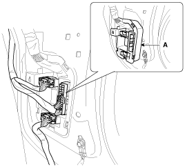
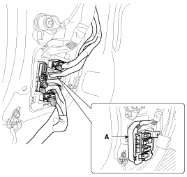
| 14. |
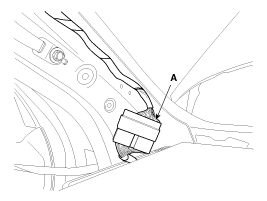
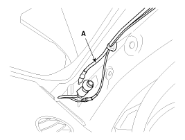
Remove the left & right filler trim and than disconnect the connector (A).
|
| 15. |
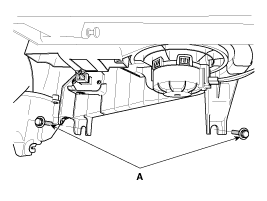
Remove the heater & blower unit after loosening mounting bolts (A).
|
| 16. |
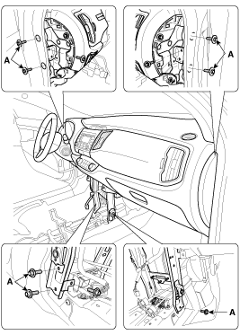
Loosen the cowl cross member mounting bolts (A) and then remove the crash pad and heater blower unit.
|
| 17. |
Disconnect the connectors and then remove the heater blower unit (A) from crash pad.
|
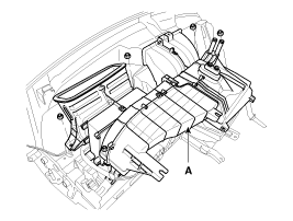
| 18. |
Remove the blower unit (A) from heater unit (B) after loosening screws.
|
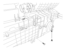
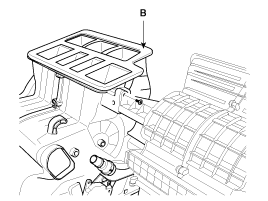
| 19. |
Loosen the mounting screw and then remove the heater core cover (A).
|
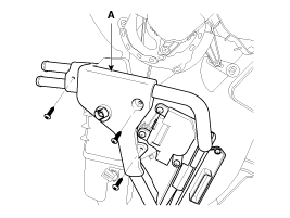
| 20. |
Disconnect the heater core (A) from heater unit.
|
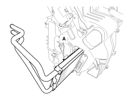
| 21. |
Loosen the heater unit lower case mount screw and then remove the heater unit lower case (A).
|
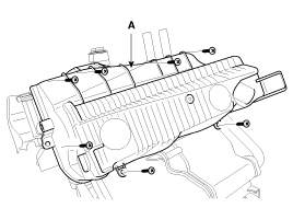
| 22. |
Remove the evaporator core (A).
|
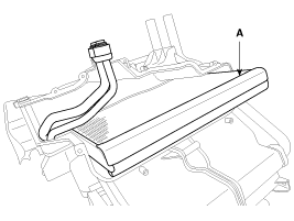
| 23. |
Be careful that the inlet and outlet pipe are not bent during heater core removal, and pull out the heater core. |
| 24. |
Installation is the reverse order of removal. |
| 25. |
Installation is the reverse order of removal, and note these items :
|
Component Location
Components
1. Heater Case (LH)2. Heater Case (RH)3. Heater Lower Case4. Separator5. Shower Duct6. Heater Core7. Evaporator Core8. Evaporator Sensor9. Vent Door10. Vent Door11....
 Heater Unit: Components and Components Location
Component Location...
 Temperature Control Actuator: Components and Components Location
See also:
Condenser: Components and Components Location
Component Location
...
Fuel Tank Pressure Sensor (FTPS): Schematic Diagrams
Circuit Diagram
...
ESC OFF usage
When driving
It’s a good idea to keep the ESC turned on for daily driving whenever possible.
To turn ESC off while driving, press the ESC OFF button while driving on
a flat road surface.
...
Categories
- Home
- Kia Sportage NQ5 (2022-2026) Owner's Manual
- Kia Sportage QL (2015-2019) Owner's Manual
- Kia Sportage QL (2015-2019) Service Manual
- Kia Sportage SL 2010-2016 Owner's Manual
- Kia Sportage SL 2010-2016 Service Manual

Copyright © sl.kispmanual.com 2014-2026 - 0.0542