
 Kia Sportage: Smart key unit: Schematic Diagrams
Kia Sportage Service & Repair Manual (3rd Generation, SL; 2011-2016) / Body Electrical System / Smart key System / Smart key unit: Schematic Diagrams
| Circuit Diagram |
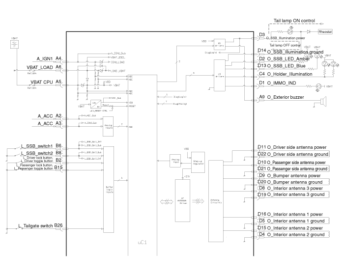
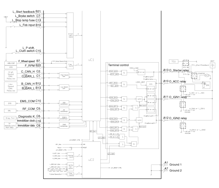
Components
Connector Pin Information
NoConnector A (14 Pin)NoConnector B (26 Pin)1Ground 11 -15L_Passenger lock button, L_Passenger toggle button2A_ACC2L_Driver lock button,L_Driver toggle ...
 Smart key unit: Components and Components Location
Removal
Smart Key Unit
1.
Disconnect the negative (-) battery terminal.
2.
Remove the glove box.
(Refer to the BD group - "Crash pad")
3.
After disconnecting the smart key unit connector...
 Smart key unit: Repair procedures
See also:
Transaxle Control Module (TCM): Description and Operation
Description
Transaxle Control Module (TCM) is the automatic
transmission''s brain. The module receives and processes signals from
various sensors and implements a wide range of transmission con ...
Line Pressure Control Solenoid Valve: Description and Operation
Description
line pressure control solenoid valve is attached to the valve
body. This variable force solenoid valve directly controls the
hydraulic pressure inside the line pressure. ...
Front Impact Sensor (FIS): Components and Components Location
Components
...
Categories
- Home
- Kia Sportage NQ5 (2022-2026) Owner's Manual
- Kia Sportage QL (2015-2019) Owner's Manual
- Kia Sportage QL (2015-2019) Service Manual
- Kia Sportage SL 2010-2016 Owner's Manual
- Kia Sportage SL 2010-2016 Service Manual

Copyright © sl.kispmanual.com 2014-2026 - 0.0676