
 Kia Sportage: Intake Manifold: Repair procedures
Kia Sportage Service & Repair Manual (3rd Generation, SL; 2011-2016) / Engine Mechanical System / Intake And Exhaust System / Intake Manifold: Repair procedures
| Removal and Installation |
| 1. |
Remove the engine cover. |
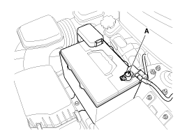
| 2. |
Disconnect the battery negative terminal (A).
|
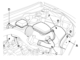
| 3. |
Remove the air cleaner assembly.
|
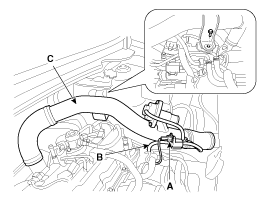
| 4. |
Disconnect the recirculation valve connector (A) and the
vacuum hose (B), and then remove the intercooner inlet pipe & hose
assembly (C).
|
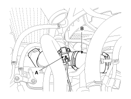
| 5. |
Disconnect the boost pressure sensor connector (A) and then remove the intercooler outlet pipe & hose assembly (B).
|
| 6. |
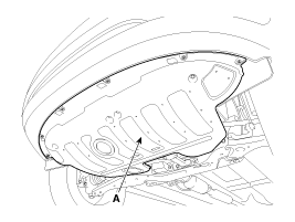
Remove the under cover (A).
|
| 7. |
Loosen the drain plug, and drain the engine coolant. Remove
the radiator cap to drain with speed. (Refer to Cooling system in this
group) |
| 8. |
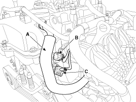
Disconnect the PCV hose (A), the intake OCV (Oil control
valve) connector (B) and the OTS (Oil temperature sensor) connector (C).
|
| 9. |
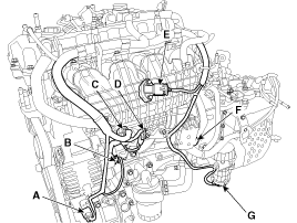
Disconnect the A/C compressor switch connector (A), the
alternator connector (B), the OPS (Oil pressure switch) connector &
injector extension connector (C), the knock sensor connector (D), the
MAPS (Manifold absolute pressure sensor) & IATS (Intake air
temperature sensor) connector (E), the ETC (Electronic throttle control)
connector (F) and the vacuum pump connector (G).
|
| 10. |
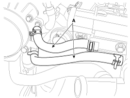
Disconnect the throttle body coolant hoses (A).
|
| 11. |
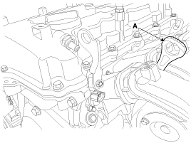
Remove the oil level gauge (A).
|
| 12. |
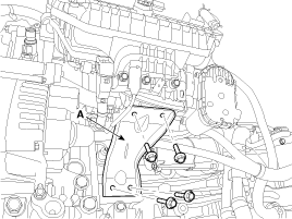
Remove the intake manifold stay (A).
|
| 13. |
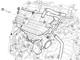
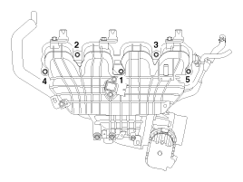
Remove the intake manifold (A) after disconnecting the vacuum hoses.
When installing the intake manifold, tighten the bolts and
nuts with pre-torque first, and then tighten the bolts and nuts with
specified torque in the sequence shown.
|

| 14. |
Installation is reverse order of removal. |
Components
1. Intake manifold assembly 2. Electronic throttle body3. Intake manifold stay4. Intake manifold gasket...
 Intake Manifold: Components and Components Location
Components
1. Hear protector2. EWGA(Electric Waste Gate Actuator)3. C-ring4. Turbo manifold module5. Turbocharger stay6. Trubo adapter gasket7. Turbo adapter8. Turbo adapter heat protector9. Oil ...
 Exhaust Manifold: Components and Components Location
See also:
Injured person
A seat belt should be used when an injured person is being transported. When
this is necessary, you should consult a physician for recommendations. ...
All season tires
Kia specifies all season tires on some models to provide good performance for
use all year round, including snowy and icy road conditions. All season tires are
identified by ALL SEASON and/or M+S ...
Rain Sensor: Repair procedures
Inspection
Rain Sensing Wiper
1.
In IGN2 ON state, if auto switch input (LIN communication) is
ON then both wiper low relay and wiper high relay outputs are
controlled by the rain sensor inpu ...
Categories
- Home
- Kia Sportage NQ5 (2022-2026) Owner's Manual
- Kia Sportage QL (2015-2019) Owner's Manual
- Kia Sportage QL (2015-2019) Service Manual
- Kia Sportage SL 2010-2016 Owner's Manual
- Kia Sportage SL 2010-2016 Service Manual

Copyright © sl.kispmanual.com 2014-2026 - 0.0651