
 Kia Sportage: Line Pressure Control Solenoid Valve: Repair procedures
Kia Sportage Service & Repair Manual (3rd Generation, SL; 2011-2016) / Automatic Transaxle System / Automatic Transaxle Control System / Line Pressure Control Solenoid Valve: Repair procedures
| Inspection |
| 1. |
Turn ignition switch OFF. |
| 2. |
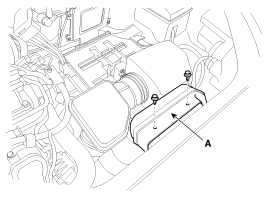
Remove the air duct (A).
|
| 3. |
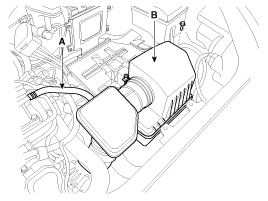
Remove the air cleaner assembly.
|
| 4. |
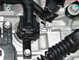
Disconnect the solenoid valve connector (A).
|
| 5. |
Measure resistance between sensor signal terminal and ground terminal. |
| 6. |
Check that the resistance is within the specification. |
| Removal |
Replacing an on/off solenoid valve (SS-A, SS-B) does not
require additional hydraulic pressure adjustment; however, the hydraulic
pressure will need to be adjusted after replacing the VFS solenoid
valve. If replacing the VFS solenoid valve; also replace the valve body
assembly.
(Refer to "Valve Body" in Hydraulic System of this group) |

Circuit Diagram...
 Line Pressure Control Solenoid Valve: Schematic Diagrams
Description
35R Clutch control solenoid valve(35R/C) is attached to the
valve body. This variable force solenoid valve directly controls the
hydraulic pressure inside the 35R Clutch....
 35R Clutch Control Solenoid Valve(35R/C_VFS): Description and Operation
See also:
PDM Relay Box: Description and Operation
Description
The PDM relay (A) is united with IG1, IG2 and ACC relays and installed in the lower center fascia panel. ...
Manual climate control system
1.Turn the ignition switch to the ON position.
2.Turn the mode selection knob to the defrost position ().
3.Press the air intake control button at least 5 times within 3 seconds.
The indicator li ...
Schematic Diagrams
Circuit Diagram - ESC(1)
Circuit Diagram - ESC(2)
Circuit Diagram - ESC(3)
ESC connector input/output
Connector TerminalSpecificationRemarkNoDescription29IGNITION1(+)High level of wake up vol ...
Categories
- Home
- Kia Sportage NQ5 (2022-2026) Owner's Manual
- Kia Sportage QL (2015-2019) Owner's Manual
- Kia Sportage QL (2015-2019) Service Manual
- Kia Sportage SL 2010-2016 Owner's Manual
- Kia Sportage SL 2010-2016 Service Manual

Copyright © sl.kispmanual.com 2014-2026 - 0.0613