
 Kia Sportage: Schematic Diagrams
Kia Sportage Service & Repair Manual (3rd Generation, SL; 2011-2016) / Brake System / ESC(Electronic Stability Control) System / Schematic Diagrams
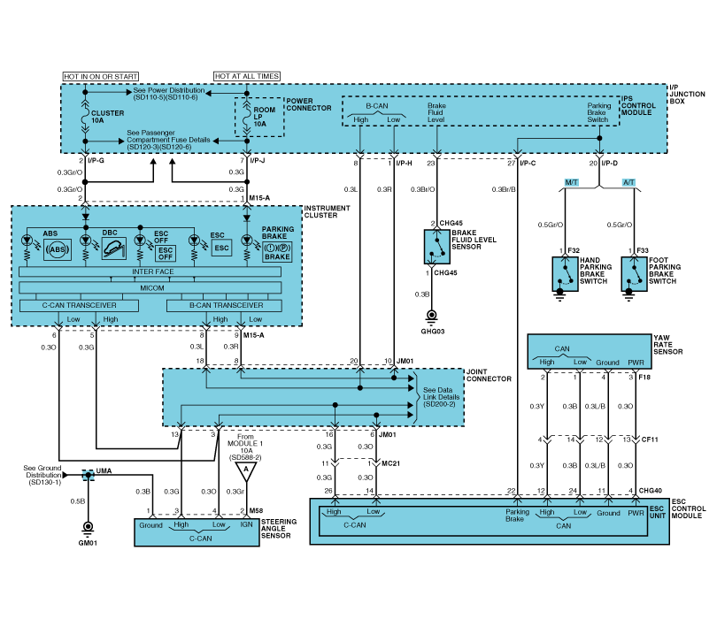
| Circuit Diagram - ESC(1) |
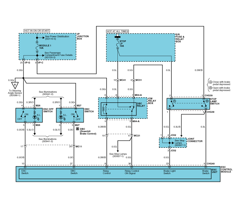
| Circuit Diagram - ESC(2) |
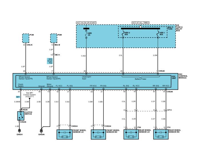
| Circuit Diagram - ESC(3) |
| ESC connector input/output |
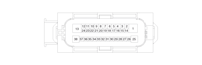
| Connector Terminal | Specification | Remark | |
| No | Description | ||
| 29 | IGNITION1(+) | High level of wake up voltage : 4.5V < V < 16.0V Low level of wake up voltage : V < 2.4V Max. current : I < 50mA | |
| 25 | POS. BATTERY 1.(SOLENOID) | Over voltage range : 17.0 ± 0.5V Operating voltage range : 10.0 ± 0.5V < V < 16.0 ± 0.5V Low voltage range : 7.0 ± 0.5V < V < 9.5 ± 0.5V Max. current : I < 40A Max. leakage current : I < 0.25mA | |
| 1 | POS. BATTERY 2.(MOTOR) | Operating voltage range: 10.0 ± 0.5V < V < 16.0 ± 0.5V Rush current : I < 110A Max current : I < 40A Max leakage current : I < 0.25mA | |
| 38 | GROUND | Rated current : I <550mA Max. current: I < 40A | |
| 13 | PUMP MOTOR GROUND | Rush current : I < 110A Max current : I < 40A | |
| 11 | SENSOR GROUND | Rated current : I <250mA | |
| 4 | SENSOR POWER | Max current Capability : I < 250mA Max voltage : V_BAT1 -0.8V | |
| 23 | BRAKE LIGHT SWITCH | Input voltage (Low) : V < 2V Input voltage (High) : V > 6V Max. Input current : I < 3mA | |
| 9 | BRAKE SWITCH | ||
| 22 | PARKING BRAKE SWITCH | Input voltage (Low) : V < 2V Input voltage (High) : V > 6V Max input current : I < 5mA | |
| 35 | CLUTCH SWITCH (M/T Only) | ||
| 28 | SENSOR FRONT RIGHT OUTPUT | External pull up resistance :1 K? < R Output duty : 50 ± 20% | |
| 17 | SENSOR REAT RIGHT OUTPUT | ||
| 10 | ESC ON/OFF SWITCH | Input voltage (Low) : V < 2V Input voltage (High) : V > 6V Max input current : I <3mA | |
| 37 | DBC SWITCH | ||
| 14 | CAN BUS LINE(LOW) | Max. Input current : I < 10mA | |
| 26 | CAN BUS LINE(HIGH) | ||
| 18 | SENSOR FRONT LEFT POWER | Output voltage : V_BAT1 -0.6V ~ V_BAT1 -1.1V Output current : Max 30mA | |
| 34 | SENSOR FRONT RIGHT POWER | ||
| 19 | SENSOR REAR LEFT POWER | ||
| 33 | SENSOR REAR RIGHT POWER | ||
| 31 | SENSOR FRONT LEFT SIGNAL | Input current LOW : 5.9 ~ 8.4mA Input current HIGH : 11.8 ~ 16.8mA Frequency range : 1 ~ 2500Hz Input duty : 50 ± 10% | Typ. 7mA Typ. 14mA |
| 21 | SENSOR FRONT RIGHT SIGNAL | ||
| 32 | SENSOR REAR LEFT SIGNAL | ||
| 20 | SENSOR REAR RIGHT SIGNAL | ||
| 12 | CAN SENSOR LINE (HIGH) | Max. input current : I < 10mA | |
| 24 | CAN SENSOR LINE (LOW) | ||
| 8 | BRAKE RELAY | Max. current : I < 180mA Max. Output low voltage : V < 1.2V | |
| 36 | RELAY STATE MONITORING | Input voltage (Low) : V < 2V Input voltage (High) : V > 6V Max Input current : I <10mA | |
Description of ESC
Optimum driving safety now has a name : ESC, the Electronic Stability Control.
ESC recognizes critical driving conditions, such as panic
reactions in dangerous situations, a...
 Description and Operation
Failure Diagnosis
1.
In principle, ESC and TCS controls are prohibited in case of ABS failure.
2.
When ESC or TCS fails, only the failed system control is prohibited.
3.
The solenoid valve...
 Troubleshooting
See also:
Fuel Tank Pressure Sensor (FTPS): Repair procedures
Inspection
1.
Connect the GDS on the Data Link Connector (DLC).
2.
Measure the output voltage of the FTPS.
Specification: Refer to "Specification"
Removal
1.
Turn the ignition swit ...
Front fog light
Fog lights are used to provide improved visibility when visibility is poor due
to fog, rain or snow, etc. The fog lights will turn on when the fog light switch
(1) is turned to the on position a ...
AUX(Auxiliary) Jack: Repair procedures
Removal
1.
Remove the knob. Remove the floor console upper cover (A) using the appropriate tool.
(Refer to the BD group - "Console")
2.
Loosen screws (2EA) and remove the floor console tray ( ...
Categories
- Home
- Kia Sportage NQ5 (2022-2026) Owner's Manual
- Kia Sportage QL (2015-2019) Owner's Manual
- Kia Sportage QL (2015-2019) Service Manual
- Kia Sportage SL 2010-2016 Owner's Manual
- Kia Sportage SL 2010-2016 Service Manual

Copyright © sl.kispmanual.com 2014-2026 - 0.0589