
 Kia Sportage: Schematic Diagrams
Kia Sportage Service & Repair Manual (3rd Generation, SL; 2011-2016) / Body Electrical System / Auto Lighting Control System / Schematic Diagrams
| Circuit Diagram |
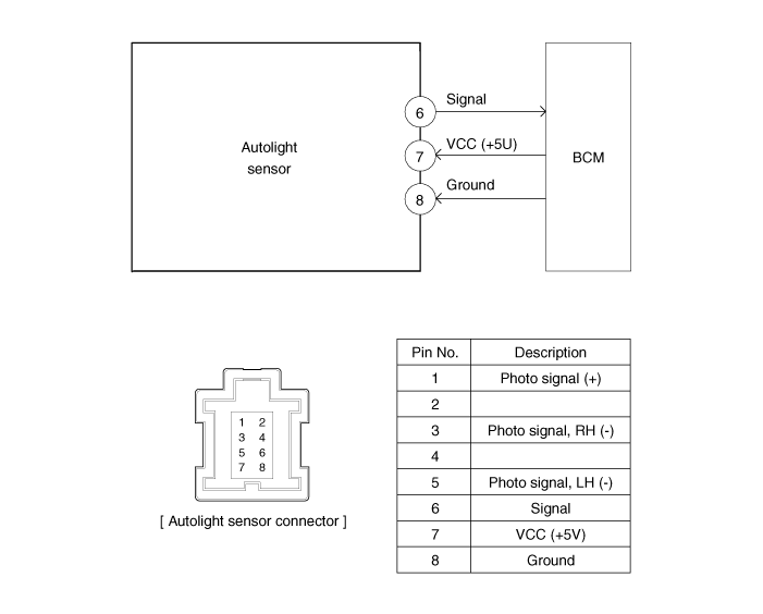
Component Location
1. Auto light sensor2. Head lamps3. Lighting switch (Auto)4. Tail lamps5. SJB (Smart Junction Box)6. BCM (Body Control Module)...
 Components and Components Location
Description
This function describes the following features
–
Input detection by Auto Light Sensor.
–
Generate Auto Light Out Status data.
–
Send Auto Light Out Sta...
 Description and Operation
See also:
ICM (Integrated Circuit Module) Relay Box: Schematic Diagrams
Schematic Diagram
...
ESC (Electronic Stability Control) indicator
The ESC indicator will illuminate when the ignition switch is turned ON, but
should go off after approximately 3 seconds. When the ESC is on, it monitors the
driving conditions and under normal ...
Checking the engine oil level
1.Be sure the vehicle is on level ground.
2.Start the engine and allow it to reach normal operating temperature.
3.Turn the engine off and wait for a few minutes (about 5 minutes) for the oil
to r ...
Categories
- Home
- Kia Sportage NQ5 (2022-2026) Owner's Manual
- Kia Sportage QL (2015-2019) Owner's Manual
- Kia Sportage QL (2015-2019) Service Manual
- Kia Sportage SL 2010-2016 Owner's Manual
- Kia Sportage SL 2010-2016 Service Manual

Copyright © sl.kispmanual.com 2014-2026 - 0.0627