
 Kia Sportage: Seat Heater: Repair procedures
Kia Sportage Service & Repair Manual (3rd Generation, SL; 2011-2016) / Body Electrical System / Seat Electrical / Seat Heater: Repair procedures
| Removal |
| 1. |
Remove the seat back cover and cushion cover.
(Refer to the BD group - "Front seat") |
| 2. |
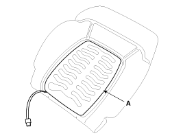
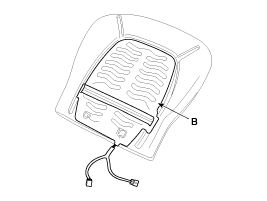
Remove the driver / assist seat back heater (A) and cushion heater (B).
|
| 3. |
Remove the cushion cover of rear seat.
(Refer to the BD group - "Rear seat") |
| 4. |
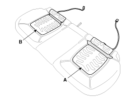
Remove the heater (A) of rear seat (LH) and the heater (B) of rear seat (RH).
|
| Installation |
| 1. |
Install the driver / assist seat back and cushion heater.
(Refer to the BD group - "Front seat") |
| 2. |
Install the heater of rear seat (LH & RH).
(Refer to the BD group - "Rear seat") |
| Inspection |
Driver / Assist Seat
| 1. |
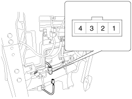
Check for continuity and measure the resistance between terminals as below.
|
| 2. |
Operate seat warmer after connecting the 4P connector, and
then check the thermostat by measuring the temperature of seat surface.
|
Rear Seat
| 1. |
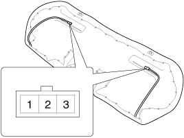
Check for continuity and measure the resistance between terminal 2 and 3.
|
| 2. |
Operate seat warmer after connecting the 4P connector, and
then check the thermostat by measuring the temperature of seat surface.
|
Component Location...
 Seat Heater: Components and Components Location
Components
1. Ventilation blower2. Ventilation ECU3. Ventilation seat switch4. Blower connector5. Heater connector6. Ventilation ECU connector...
 Climate Seat: Components and Components Location
See also:
Schematic Diagrams
Circuit Diagram (1)
Circuit Diagram (2)
Harness Connector
Pin Function (Connector A)Pin Function (Connector A)1Ignition1Pressure side impact sensor [Driver] High2 -2Side impact ...
Side impact air bag
Your vehicle is equipped with a side impact air bag in each front seat.
The purpose of the air bag is to provide the vehicle's driver and/or the front
passenger with additional protection t ...
Automatic Transaxle: Repair procedures
Removal
1.
Remove the following items;
•
Engine cover (A).
•
Air cleaner assembly and air duct (B). (Refer to "Intake and Exhaust system" in EM group.)
•
Batter ...
Categories
- Home
- Kia Sportage NQ5 (2022-2026) Owner's Manual
- Kia Sportage QL (2015-2019) Owner's Manual
- Kia Sportage QL (2015-2019) Service Manual
- Kia Sportage SL 2010-2016 Owner's Manual
- Kia Sportage SL 2010-2016 Service Manual

Copyright © sl.kispmanual.com 2014-2026 - 0.0679