
 Kia Sportage: SS-B Solenoid Valve(ON/OFF): Repair procedures
Kia Sportage Service & Repair Manual (3rd Generation, SL; 2011-2016) / Automatic Transaxle System / Automatic Transaxle Control System / SS-B Solenoid Valve(ON/OFF): Repair procedures
| Inspection |
| 1. |
Turn ignition switch OFF. |
| 2. |
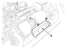
Remove the air duct (A).
|
| 3. |
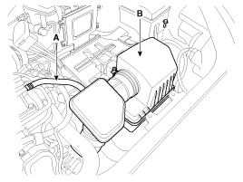
Remove the air cleaner assembly.
|
| 4. |
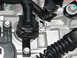
Disconnect the solenoid valve connector (A).
|
| 5. |
Measure resistance between sensor signal terminal and ground terminal. |
| 6. |
Check that the resistance is within the specification. |
| Removal |
| 1. |
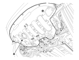
Remove the under cover (A).
|
| 2. |
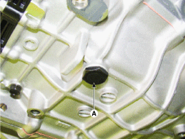
Remove the drain plug (A) and drain the ATF totally and then reinstall the drain plug.
|

| 3. |
Remove the air duct (A).
|
| 4. |
Remove the air cleaner assembly.
|
| 5. |
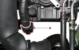
Disconnect the clip (A) from the valve body cover.
|
| 6. |
Remove the air breather hose (A). |
| 7. |
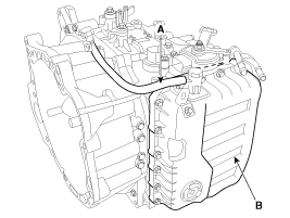
Remove t he valve body cover (B).
|
| 8. |
Remove the solenoid valve connector (B) and the oil temperature sensor (A).
|
| 9. |
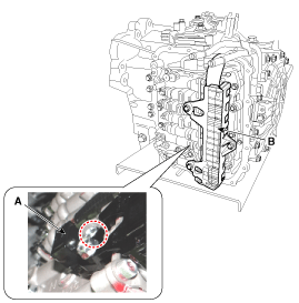
Remove the solenoid valve (B) after removing the solenoid support bracket (A).
|
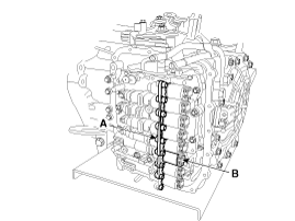
| Installation |
| 1. |
Installation is the reverse of removal.
|
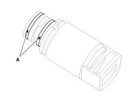
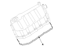
Circuit Diagram...
 SS-B Solenoid Valve(ON/OFF): Schematic Diagrams
Description
Inhibitor Switch monitors the lever''s position(P, R, N, D) and is used to control gear setting signals....
 Inhibitor Switch: Description and Operation
See also:
Intake Air Temperature Sensor (IATS): Specifications
Specification
TemperatureResistance (k?)°C°F-40-4040.93 ~ 48.35-20-413.89 ~ 16.030325.38 ~ 6.0910503.48 ~ 3.9020682.31 ~ 2.57401041.08 ~ 1.21501221.56 ~ 1.74601400.54 ~ 0.62801760.29 ~ 0.34
...
Cylinder Block: Components and Components Location
Components
1. Piston ring2. Snap ring3. Piston4. Connecting rod 5. Connecting rod upper bearing6. Piston pin7. Connecting rod lower bearing8. Connecting rod bearing cap9. Ladder frame10. Oil filt ...
Front Impact Sensor (FIS): Repair procedures
Removal
•
Removal of the airbag must be performed according to the precautions/ procedures described previously.
•
Before disconnecting the front i ...
Categories
- Home
- Kia Sportage NQ5 (2022-2026) Owner's Manual
- Kia Sportage QL (2015-2019) Owner's Manual
- Kia Sportage QL (2015-2019) Service Manual
- Kia Sportage SL 2010-2016 Owner's Manual
- Kia Sportage SL 2010-2016 Service Manual

Copyright © sl.kispmanual.com 2014-2026 - 0.059